SICK ASIC technology - the result of decades of experience in photoelectric sensors
Large, user-friendly potentiometer
Large, bright indicator LEDs
adjustable receiver sensitivity via 270° turn potentiometer (depending on type)
IP 67 enclosure rating
Your benefits
Easy alignment and precise object detection due to a highly visible PinPoint LED
Quick and easy mounting and high durability due to threaded metal inserts
SICK ASIC technology provides high performance and excellent reliability
Easy to adjust due to large, user-friendly potentiometers
Easy to monitor due to large, bright indicator LEDs
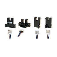
Easy installation with SICK accessories
Features
Sensor/detection principle:
Through-beam photoelectric sensor
Dimensions (W x H x D):
12 mm x 31.5 mm x 21 mm
Housing design (light emission):
Rectangular
Sensing range max.:
0 m ... 15 m
Sensing range:
0 m ... 10 m
Type of light:
Visible red light
Light source:
PinPoint LED 1)
Wave length:
650 nm
Light spot size (distance):
Ø 375 mm (12 m)
1) Average service life of 100,000 h at TA = +25 °C
Mechanics/electronics
Supply voltage:
10 V DC ... 30 V DC 1)
Residual ripple:
± 10 % 2)
Power consumption:
≤ 30 mA 3)
Output type:
NPN, open collector
Switching mode:
Light/dark switching
Switching mode selector:
Selectable via light/dark selector
Output current Imax.:
≤ 100 mA 4)
Response time:
< 500 µs 5)
Switching frequency:
1,000 Hz 6)
Connection type:
Cable, 3-wire, 2 m 7)
Cable material:
PVC
Conductor cross-section:
0.14 mm²
Circuit protection:
A, B, D 8)9)10)
Protection class:
III
Weight:
170 g
Polarisation filter:
-
Optics material:
PMMA
Enclosure rating:
IP 67
Ambient operating temperature:
-25 °C ... +55 °C 11)
Ambient storage temperature:
-40 °C ... +70 °C
UL File No.:
NRKH.E348498 & NRKH7.E348498
Signal voltage NPN HIGH/LOW:
Approx. VS / ≤ 3 V
Housing material:
ABS/PC, Plastic
1) Limit values, operation in short-circuit protected network max. 8 A 2) May not exceed or fall short of VS tolerances 3) Without load 4) At Vs > 24 V, IA max = 50 mA 5) Signal transit time with resistive load 6) With light/dark ratio 1:1 7) Do not bend below 0 °C 8) A = VS connections reverse-polarity protected 9) B = inputs and output reverse-polarity protected 10) D = outputs overcurrent and short-circuit protected 11) Temperature stability after adjustment +/-10°C


 在線客服
在線客服
 企業微信
企業微信


 [VIP第3年] 指數:2
 通過認證
通過認證